|
|
|
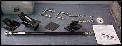
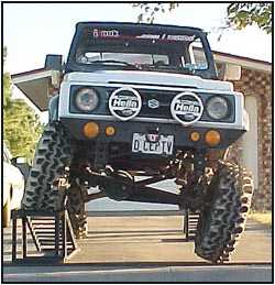
Panhard Kit Installation
With Bill Johnston
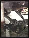
 Ever turned the steering
wheel and watched the tire actually move over instead of turn? If you have
a 'flexy' suspension, it usually absorbs some of the lateral movement of
the steering system before it is transferred to turning the tires. Here's an
example... Have you ever driven down the road and wiggled the
steering wheel back and forth without noticing any change in the direction
you are going? Before this installation, our Samurai's steering wheel
moved a good six inches without effecting the swampers. The Spidertrax
Panhard Kit is designed to take away that lack of control. Currently
the kit is only available for SPring Over
Axle converted Samurais. Ever turned the steering
wheel and watched the tire actually move over instead of turn? If you have
a 'flexy' suspension, it usually absorbs some of the lateral movement of
the steering system before it is transferred to turning the tires. Here's an
example... Have you ever driven down the road and wiggled the
steering wheel back and forth without noticing any change in the direction
you are going? Before this installation, our Samurai's steering wheel
moved a good six inches without effecting the swampers. The Spidertrax
Panhard Kit is designed to take away that lack of control. Currently
the kit is only available for SPring Over
Axle converted Samurais.
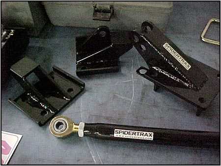
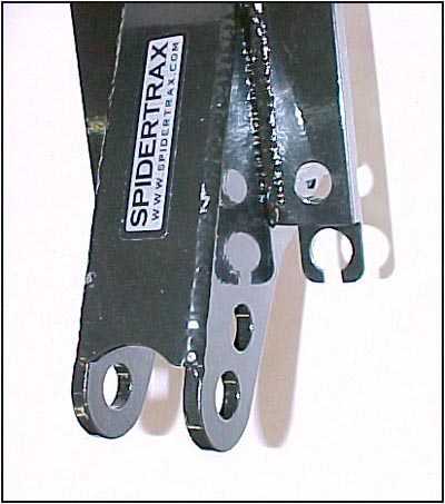
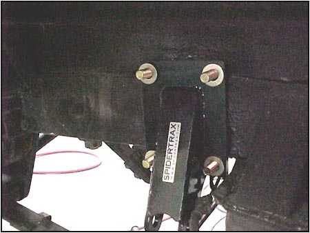
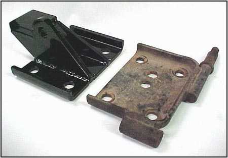
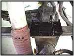
 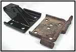 Here you can see the built in bump
stop shelves in the
new u-bolt plates.
You may also notice the second centering pin hole that had been
drilled into the stock plate. This is a common variation seen when
the axle has been moved forward to increase the vehicle's wheelbase.
The guys at Spidertrax took this into consideration while designing
the new Here you can see the built in bump
stop shelves in the
new u-bolt plates.
You may also notice the second centering pin hole that had been
drilled into the stock plate. This is a common variation seen when
the axle has been moved forward to increase the vehicle's wheelbase.
The guys at Spidertrax took this into consideration while designing
the new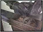 component. There are three different centering pin holes to
allow you to match your application. component. There are three different centering pin holes to
allow you to match your application.
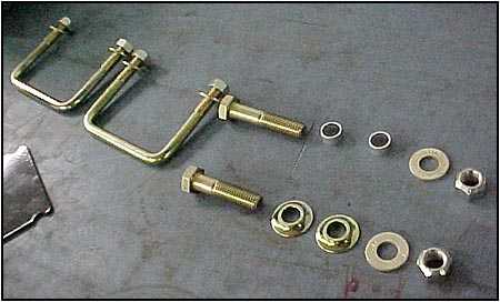
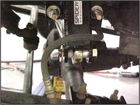
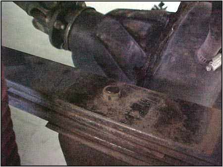
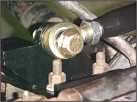
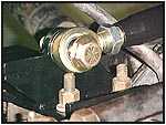
One thing we noticed, although the center hole (stock location) has
plenty of room, the other two are located under the legs of the
bumpstop shelf. This means the centering pin must be trimmed to the
top of the nut as seen to the right. |
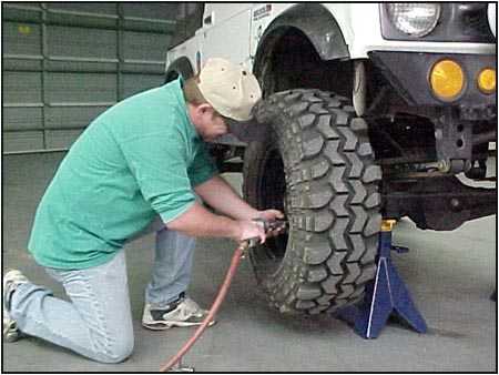
  If
you are not sure which hole to use, just set the bracket in place
and line it up directly above the axle. Re-install the stock u-bolts
and torque them to stock specs. If
you are not sure which hole to use, just set the bracket in place
and line it up directly above the axle. Re-install the stock u-bolts
and torque them to stock specs. |
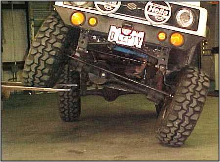
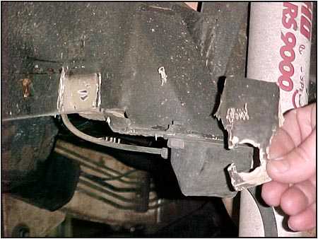
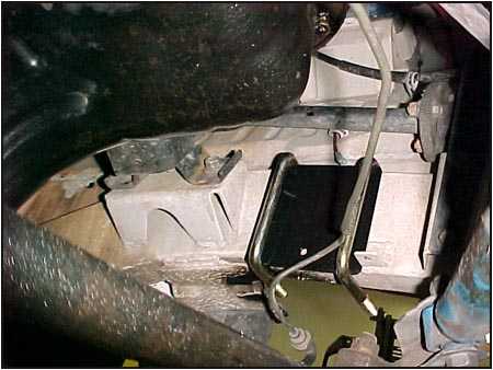
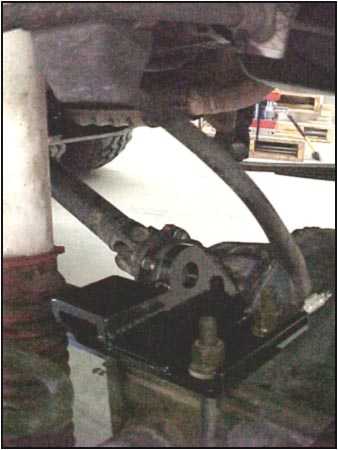
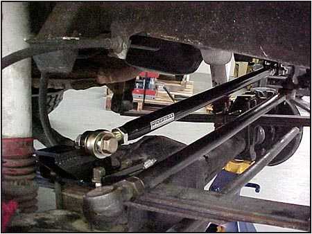
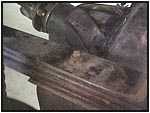
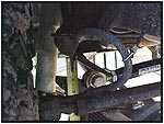
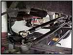  During
the trial fitting of the lower link we noticed there was not enough
room because of the longer u-bolts we used during the SPOA
conversion. These also had to be trimmed. Click on the photo to the
right and you will see how much clearance we ended up with after
trimming. You will also note how much clearance there is for
everything to else, even with the knuckle-over steering kit we
installed earlier. During
the trial fitting of the lower link we noticed there was not enough
room because of the longer u-bolts we used during the SPOA
conversion. These also had to be trimmed. Click on the photo to the
right and you will see how much clearance we ended up with after
trimming. You will also note how much clearance there is for
everything to else, even with the knuckle-over steering kit we
installed earlier. |
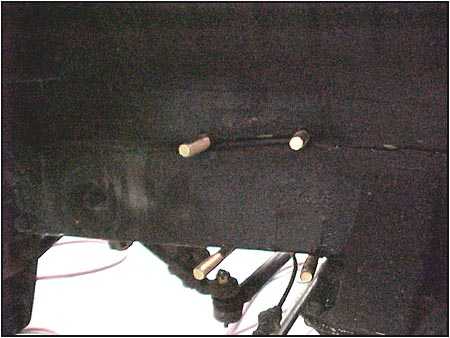
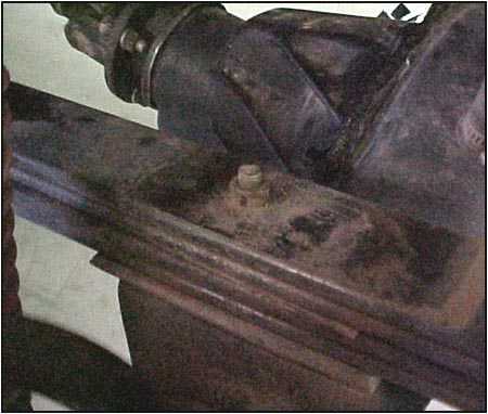
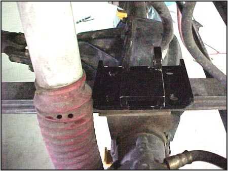
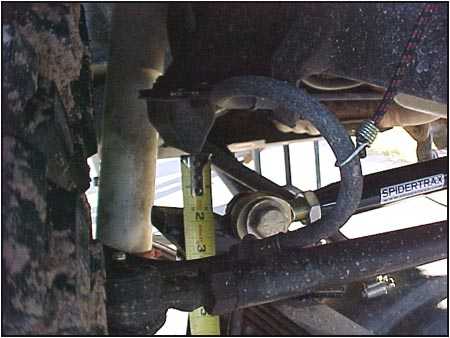
  Once everything has been installed, you need to twist up the rig as
much as possible. Check to see how close your stock rubber (upper)
bumpstops come to the new (lower) bumpstop shelf that is built into
the Spidertrax u-bolt pad. If it touches, great - your done. If
there is space like the photo above, then you need to do something
about it.
Once everything has been installed, you need to twist up the rig as
much as possible. Check to see how close your stock rubber (upper)
bumpstops come to the new (lower) bumpstop shelf that is built into
the Spidertrax u-bolt pad. If it touches, great - your done. If
there is space like the photo above, then you need to do something
about it. 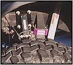 Spidertrax
has a Bumpstop Kit that uses 3/4" spacers to close the gap. We
measured 1.5" of space, so we used two of the three spacers
supplied for each side of the vehicle. The replacement bolts that
come with the bumpstop kit are long enough to accommodate all three
spacers if you need them. It is best to install the spacers first
before trimming the bolts (just in case you need to go with another
spacer). Spidertrax
has a Bumpstop Kit that uses 3/4" spacers to close the gap. We
measured 1.5" of space, so we used two of the three spacers
supplied for each side of the vehicle. The replacement bolts that
come with the bumpstop kit are long enough to accommodate all three
spacers if you need them. It is best to install the spacers first
before trimming the bolts (just in case you need to go with another
spacer). |
|
Check out the Component Review |
|
Sources for this
Spidertrax equipment:
Spidertrax
PO Box 340
New Milford, NJ 07646
www.spidertrax.com
1-800-286-0898 Orders
1-201-225-0157 Tech & Questions
1-810-821-0263 Fax
Petroworks
Box 848
Fallbrook CA 92088
www.petroworks.com
1-800-952-8915 Orders
1-760-731-9434 Tech & Questions
Rocky Road Outfitters
P.O. Box 681245
Park City, UT 84068
www.rocky-road.com
1-888-801-7271 Orders
1-435-783-2990 Tech & Questions
1-435-783-4355 Fax
|
|