|
|
ARB
Track/Kick Rear Air Locker Project Sidewinder/ARB part 2 with Bill Johnston
ARB has an air locker to fit both ring and pinion combinations that are found in the rear diffs from 1988 and up. From 1988 to 1993 Suzuki used a 10 bolt ring, this uses ARBs RD74 model. In 1993, Suzuki started putting a 12 bolt model into the rear differential. This is what we were working with, so ARB supplied the RD79 model for this installation. Both flavors of ring gear were used in 1993, so if you have any question as to what you have, there is a quick way to find out without pulling the whole thing apart.
Let me start by saying that if you are not comfortable with working on your own gearing, this is probably not the place to start unless you have someone with a little experience showing you how. If you don't set the backlash correctly, or you end up with spare parts... it will get expensive fast. |
||
  That
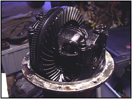
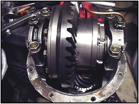
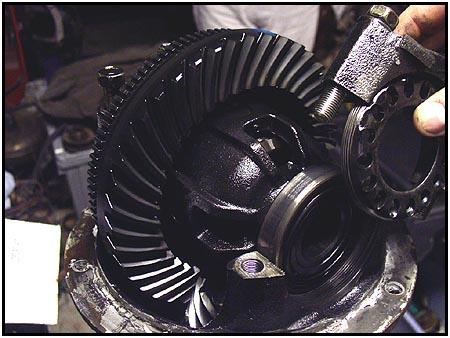
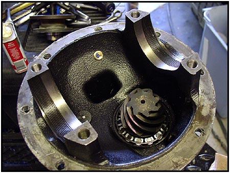
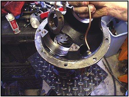
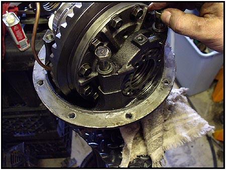
said, we started with the third member bolted to the workbench. Before
disassembly, we marked the bearing caps with a punch and then marked the
third member casing to match. One dot for the left side and two dots for
the right. That
said, we started with the third member bolted to the workbench. Before
disassembly, we marked the bearing caps with a punch and then marked the
third member casing to match. One dot for the left side and two dots for
the right. |
|||
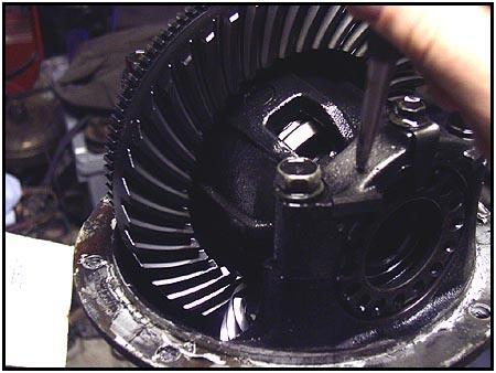
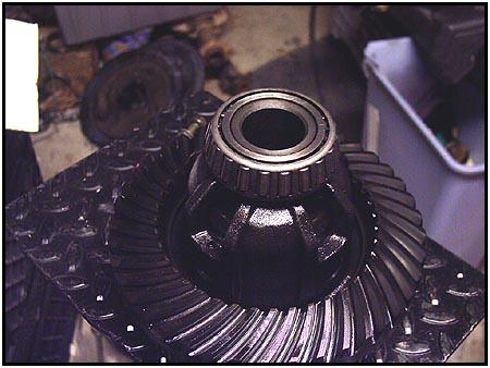
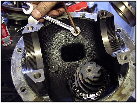
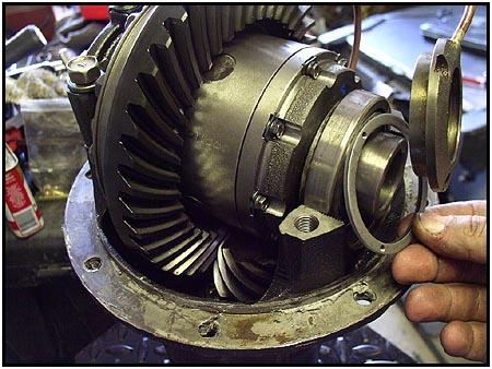
  Next
we removed the caps and set them aside. Notice the cool tool I used to
hold everything steady... I found that a birfield stub has 26 splines,
just like the rear axle. I keep two grenaded birfield stubs with my 'specialty'
tools for working with rear differentials. They are easy to hold onto and
they allow you to easily turn the splines on the bench. Next we just lift
the carrier out of the casing and move the casing to the floor. Next
we removed the caps and set them aside. Notice the cool tool I used to
hold everything steady... I found that a birfield stub has 26 splines,
just like the rear axle. I keep two grenaded birfield stubs with my 'specialty'
tools for working with rear differentials. They are easy to hold onto and
they allow you to easily turn the splines on the bench. Next we just lift
the carrier out of the casing and move the casing to the floor. |
|||
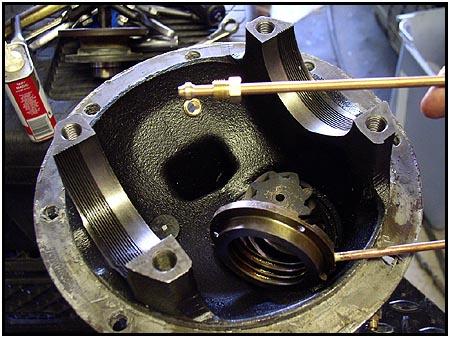
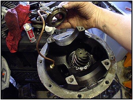
 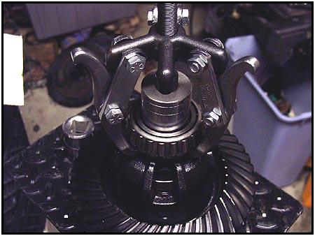 The
bearings on this carrier were in excellent shape, so we decided to reuse
them. We removed them easily using a bearing puller. Make sure you get the
ends of the arms all the way under the center portion of the bearing or
you could just rip the outer cage off - thus destroying the bearing. The
bearings on this carrier were in excellent shape, so we decided to reuse
them. We removed them easily using a bearing puller. Make sure you get the
ends of the arms all the way under the center portion of the bearing or
you could just rip the outer cage off - thus destroying the bearing. |
|||
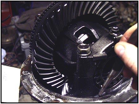
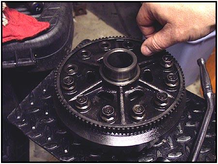
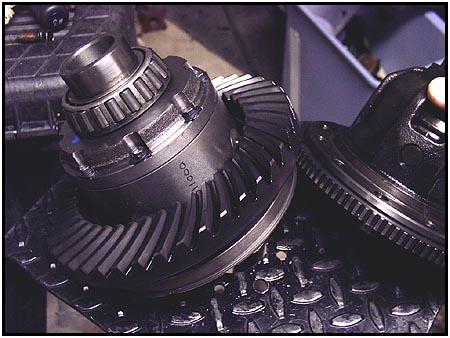
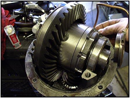
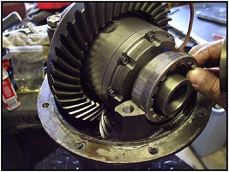
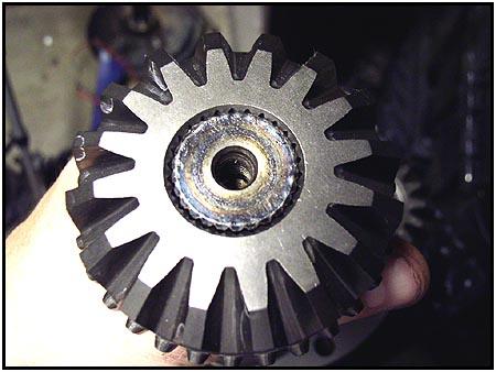
 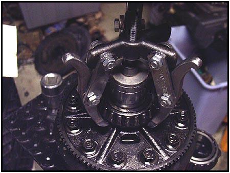 Flip
the carrier over and repeat the procedure on the other bearing. Here you
can see the 12 bolts holding the ring on the carrier. You can also see the
teeth that the speed sensor (mentioned above) counts in the photo to the
right. After reassembly, you will no longer have those teeth to worry
about. Flip
the carrier over and repeat the procedure on the other bearing. Here you
can see the 12 bolts holding the ring on the carrier. You can also see the
teeth that the speed sensor (mentioned above) counts in the photo to the
right. After reassembly, you will no longer have those teeth to worry
about. |
|||
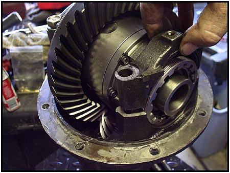
 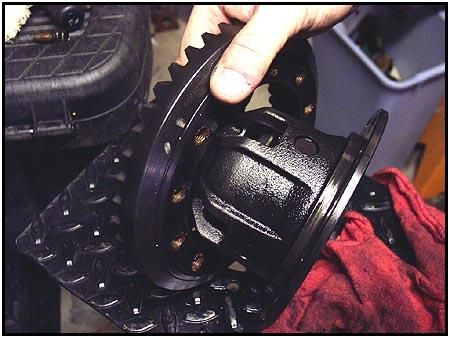 Next
we remove the ring gear bolts and carefully remove the ring gear, setting
it aside. Next
we remove the ring gear bolts and carefully remove the ring gear, setting
it aside. |
|||
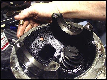
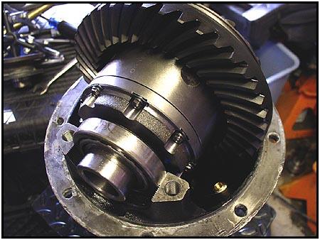
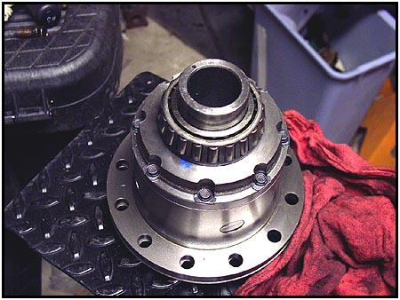  Now
we turn our attention to the ARB Air Locker. You will notice when you
press the bearings back on that one of the bearing journals is longer than
the other. This is the way they get the air into the center of the
carrier... The journal is plumbed to move air from a seal housing on the
longer section - into the heart of the carrier. This is the side that
should be facing up when you put the ring gear back on. Now
we turn our attention to the ARB Air Locker. You will notice when you
press the bearings back on that one of the bearing journals is longer than
the other. This is the way they get the air into the center of the
carrier... The journal is plumbed to move air from a seal housing on the
longer section - into the heart of the carrier. This is the side that
should be facing up when you put the ring gear back on. |
|||
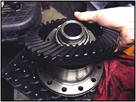
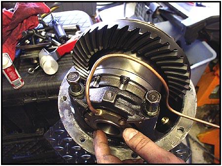
 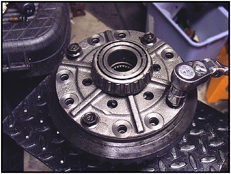 Looking
closer at the new carrier, you will notice that the flange thickness is as
thick as the old carrier (with the speed sensor gear). Since you will be
using the new carrier, the sensor gear will not be a part of the assembly.
Tighten
the bolts in a cross pattern and finish up with a torque wrench. Looking
closer at the new carrier, you will notice that the flange thickness is as
thick as the old carrier (with the speed sensor gear). Since you will be
using the new carrier, the sensor gear will not be a part of the assembly.
Tighten
the bolts in a cross pattern and finish up with a torque wrench. |
|||
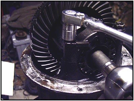
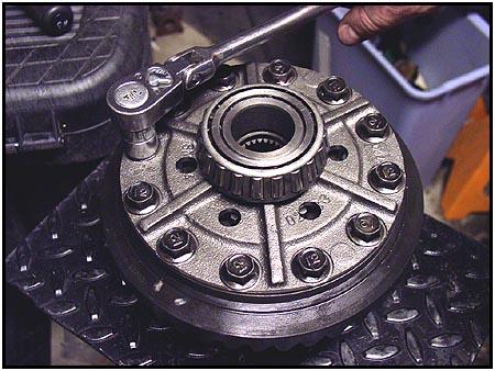  The
Factory Service Manual recommends that the ring gear (aka - drive bevel
gear) bolts get torqued to 58-66 ft-lbs. The
Factory Service Manual recommends that the ring gear (aka - drive bevel
gear) bolts get torqued to 58-66 ft-lbs.
Next you have to find the best location for the air line to enter the case. The key is to keep it away from the gears, but still make sure it clears the axle housing when the third member reinstalled. |
|||
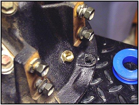
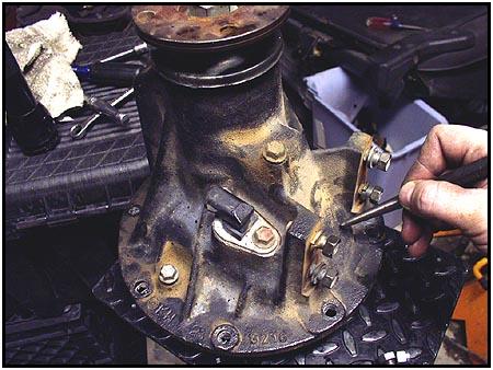  After
marking the best location with a punch, we drilled a pilot hole and then
followed it up with the 7/16" drill bit for a final hole. After
marking the best location with a punch, we drilled a pilot hole and then
followed it up with the 7/16" drill bit for a final hole. |
|||
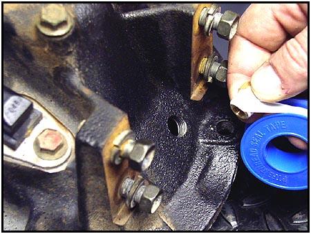
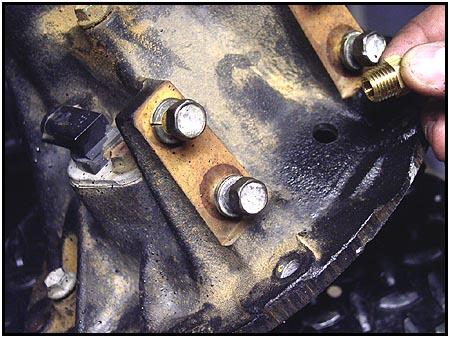  You
can see the final location once we cleaned up the hole. This is going to accommodate
a 1/4" NPT fitting, so the next step is to tap it with the
correct type of tap. This is a thin section of the case, so you don't want
to have to do this twice and run the risk of making the hole too large. You
can see the final location once we cleaned up the hole. This is going to accommodate
a 1/4" NPT fitting, so the next step is to tap it with the
correct type of tap. This is a thin section of the case, so you don't want
to have to do this twice and run the risk of making the hole too large. |
|||
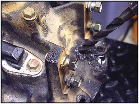
 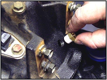 Teflon
tape should be a staple in a toolbox. Seal the threads well and install
the fitting in the new tapped location. This seal isn't for air, the
system never pressurizes the axle housing. This is more to keep all the
lubricant in the housing if you get a little radical on the trails. Teflon
tape should be a staple in a toolbox. Seal the threads well and install
the fitting in the new tapped location. This seal isn't for air, the
system never pressurizes the axle housing. This is more to keep all the
lubricant in the housing if you get a little radical on the trails. |
|||
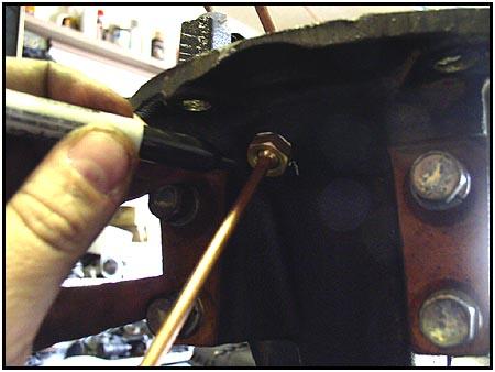
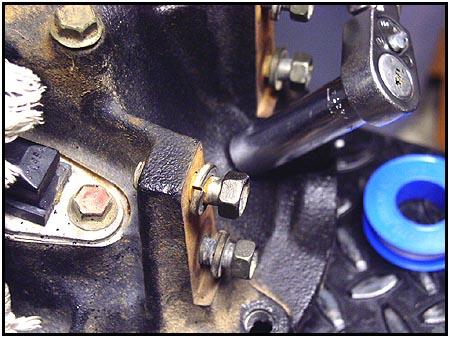  No
one likes an oil leak, especially when you were the one that did the
drilling... No
one likes an oil leak, especially when you were the one that did the
drilling...
Don't torque it down too much, remember that you want it to seal without stripping out the new threads. |
|||
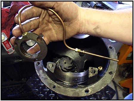
  Now
that the bulkhead body (correct name) is installed in the housing, it is
time to work on the tube that gets the air from the fitting to the locker.
Start with selecting the correct compression nut and ferrule. There are
two ferrules that come with the installation kit, but only one of them
will fit correctly on the tube. See the photo to the right. Now
that the bulkhead body (correct name) is installed in the housing, it is
time to work on the tube that gets the air from the fitting to the locker.
Start with selecting the correct compression nut and ferrule. There are
two ferrules that come with the installation kit, but only one of them
will fit correctly on the tube. See the photo to the right. |
|||
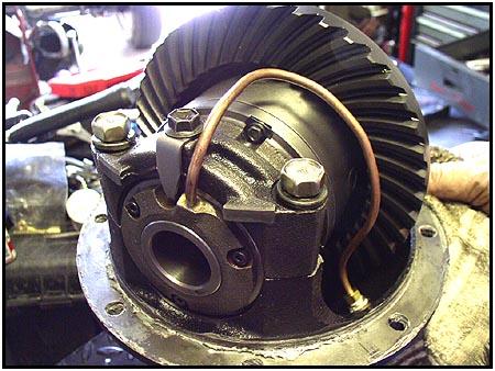
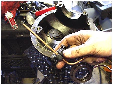
  Putting
the carrier back into place, use your hands or an appropriately sized
tubing bender to form the tube up and over the bearing cap and around the
carrier body. The seal housing (the ring on the end of the tubing) will
end up oriented with the tube coming up just to the right of the locking
tab on top of the bearing cap. Putting
the carrier back into place, use your hands or an appropriately sized
tubing bender to form the tube up and over the bearing cap and around the
carrier body. The seal housing (the ring on the end of the tubing) will
end up oriented with the tube coming up just to the right of the locking
tab on top of the bearing cap. |
|||
  While
forming the correct bends in the tubing, you can allow the seal housing to
rotate counter-clockwise a little to make room to make the final bend
where it will go into the bulkhead body that we just installed. Now we fit
the tube for trimming. While
forming the correct bends in the tubing, you can allow the seal housing to
rotate counter-clockwise a little to make room to make the final bend
where it will go into the bulkhead body that we just installed. Now we fit
the tube for trimming. |
|||
  ARB
has provided a tube that is more than long enough to take care of this
application. So we have to trim it after putting everything back into
place. A permanent marker will allow you to mark where you will have to
cut it. We suggest using a tubing cutter to make this cut, as most
anything else will deform the tube which could lead to air leaks later
on. ARB
has provided a tube that is more than long enough to take care of this
application. So we have to trim it after putting everything back into
place. A permanent marker will allow you to mark where you will have to
cut it. We suggest using a tubing cutter to make this cut, as most
anything else will deform the tube which could lead to air leaks later
on. |
|||
  We
fit the tube and seal housing in its approximate finished location and
then gently bent it out of the way so we could fir the carrier into place.
When you look around inside the empty case, you can find a couple of other
places you could mount the air tube bulkhead body. I took a look at least two where we wouldn't have to drill the case. We
fit the tube and seal housing in its approximate finished location and
then gently bent it out of the way so we could fir the carrier into place.
When you look around inside the empty case, you can find a couple of other
places you could mount the air tube bulkhead body. I took a look at least two where we wouldn't have to drill the case. |
|||
  But
neither of the locations allowed enough clearance between the ring and the
case for the line to go between with a margin of safety. So when all else
fails... follow the directions from the carrier manufacturer (which,
by the way, was very well laid out and detailed. Thanks ARB). With the air
line out of the way, the carrier goes back into place (to stay this
time). But
neither of the locations allowed enough clearance between the ring and the
case for the line to go between with a margin of safety. So when all else
fails... follow the directions from the carrier manufacturer (which,
by the way, was very well laid out and detailed. Thanks ARB). With the air
line out of the way, the carrier goes back into place (to stay this
time). |
|||
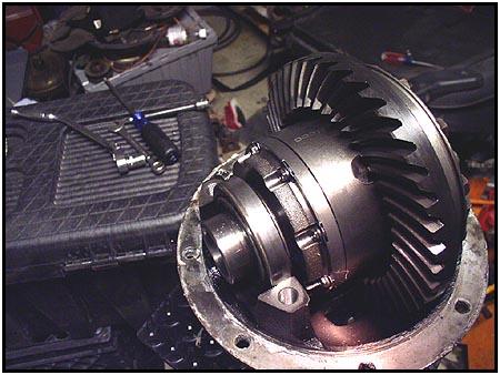
  The
easy part is the ring side of the differential. We just reassembled it
exactly the reverse of its disassembly. Don't lock down the bearing cap
bolts until you are done with backlash adjustments later. The other side
gets a bit trickier because it has to house an airtight seal for the
locker. It starts with a small clamping plate that has been tapped for
three allen screws. The
easy part is the ring side of the differential. We just reassembled it
exactly the reverse of its disassembly. Don't lock down the bearing cap
bolts until you are done with backlash adjustments later. The other side
gets a bit trickier because it has to house an airtight seal for the
locker. It starts with a small clamping plate that has been tapped for
three allen screws. |
|||
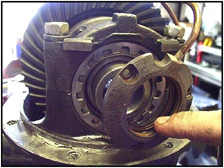
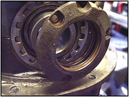
  Next
came the adjustment ring. Notice that it looks a little different than the
stock unit. Be careful when working around the extended bearing journal
because it has to be perfectly smooth and scratch free to keep the seal
air tight. Next we installed the bearing cap bolts, but, like the other
side we kept it loose enough to make the backlash adjustments needed. Next
came the adjustment ring. Notice that it looks a little different than the
stock unit. Be careful when working around the extended bearing journal
because it has to be perfectly smooth and scratch free to keep the seal
air tight. Next we installed the bearing cap bolts, but, like the other
side we kept it loose enough to make the backlash adjustments needed. |
|||
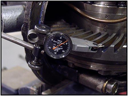 *NOTE* *NOTE*Backlash is measured with a dial indicator. The pinion must be immobilized (held perfectly still) and then the dial indicator is used to measure the amount of movement the ring gear still has. The Factory Service Manual says the measurement should be between 0.004 and 0.006 inches. The adjustment is controlled by running in one adjuster ring and running out the opposite adjuster equally. Turning the adjuster one notch changes the backlash by about 0.002 inches. |
|||
 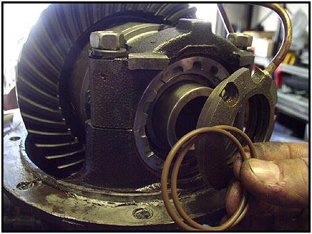 The o-rings are the most critical part of the air seal. When installed,
they create an air chamber that 'floats' on the bearing journal. The air
comes in through the seal housing and is plumbed through the journal wall
into the interior of the carrier. Give the o-rings a good coating of oil
before installing them in the seal housing. The o-rings are the most critical part of the air seal. When installed,
they create an air chamber that 'floats' on the bearing journal. The air
comes in through the seal housing and is plumbed through the journal wall
into the interior of the carrier. Give the o-rings a good coating of oil
before installing them in the seal housing. |
|||
  Also
make sure the o-rings aren't twisted in the grooves. Click on the photo to
the right (you can do this with any of the photos) to get a good look at
how the two o-rings border an air channel that we talked about
earlier. Also
make sure the o-rings aren't twisted in the grooves. Click on the photo to
the right (you can do this with any of the photos) to get a good look at
how the two o-rings border an air channel that we talked about
earlier. |
|||
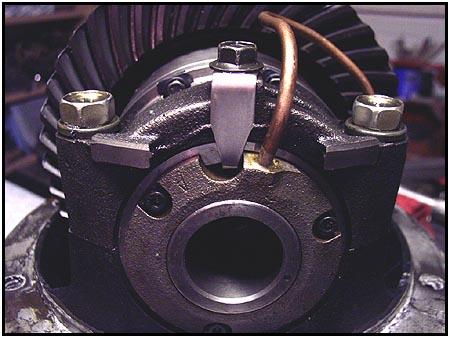
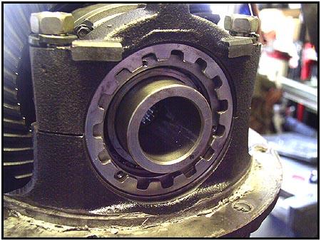
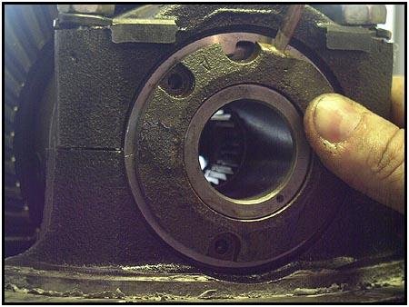  Sliding
the seal housing onto the bearing journal, you should use a gentle
twisting motion. Don't pinch the o-rings as they slide over the end. Pay
special attention to the notch just left of the air tube. This is where
the bearing adjuster stopper has to line up with an open notch on the
adjuster ring. See the center picture below to see it in place. Using
a small screwdriver we aligned the bolt holes in the seal with the tapped
holes in the clamping plate we installed at the top of this page. We added
the three cap screws using locktite to make sure things don't come loose
later on, but at this point we left them finger tight. Sliding
the seal housing onto the bearing journal, you should use a gentle
twisting motion. Don't pinch the o-rings as they slide over the end. Pay
special attention to the notch just left of the air tube. This is where
the bearing adjuster stopper has to line up with an open notch on the
adjuster ring. See the center picture below to see it in place. Using
a small screwdriver we aligned the bolt holes in the seal with the tapped
holes in the clamping plate we installed at the top of this page. We added
the three cap screws using locktite to make sure things don't come loose
later on, but at this point we left them finger tight.
Now here is a step often neglected but very important. This is where you bench test the system and center the seal housing all at the same time. Applying air (90 psi) to the system, and then rotating the carrier will center the seal housing. At this point we slowly tightened the cap screws to 3.5 ft.lbs. If you over tighten the cap screws you will deform the clamping plate and that could cause premature failure of the seal when the cap screws fall out. |
|||
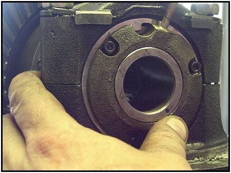
|
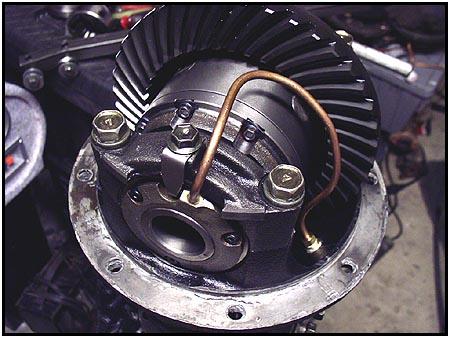
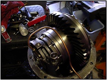
This is what it should look like when it is finished. Notice how the air tube has sweeping bends and stays away from the gear teeth. The locking tab has been put in place and the unit is ready to go into the sidewinder axle we installed in the last issue. |
|||
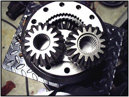
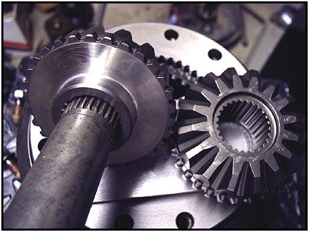
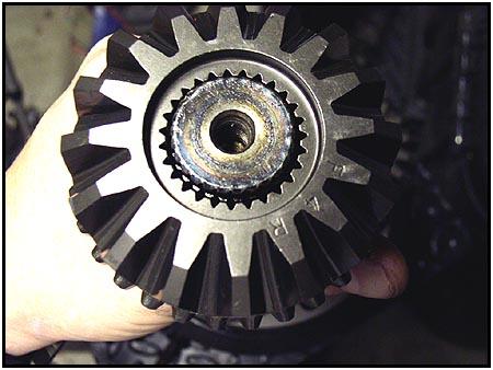  On
the left you can see the 26 spline axle in a normal ARB side gear from
this months installation. On the right you can see how much larger the
opening is in the 27 spline side gear when we put the same shaft into it.
These side gears are a direct replacement and can be ordered separately
from your ARB distributor or already installed in a new ARB air locker
prepared by the shop you get your 27 spline shafts from. On
the left you can see the 26 spline axle in a normal ARB side gear from
this months installation. On the right you can see how much larger the
opening is in the 27 spline side gear when we put the same shaft into it.
These side gears are a direct replacement and can be ordered separately
from your ARB distributor or already installed in a new ARB air locker
prepared by the shop you get your 27 spline shafts from. |
|||
  Next
issue we will show you how to convert an existing (Samurai) ARB 26 spline rear
carrier to fit the 22 spline front axle in a Samurai. That way you can
just move the ARB you spent money on last season to the front and end up
with two air lockers. Next
issue we will show you how to convert an existing (Samurai) ARB 26 spline rear
carrier to fit the 22 spline front axle in a Samurai. That way you can
just move the ARB you spent money on last season to the front and end up
with two air lockers. |
|||
|
Check out part three of this series and see how easy it is |
|||
| Source:
ARB Corporation Limited
|
03/14/2017